
There were many hopeful designs that never made it to these pages because they were not sufficiently successful (if at all) to make lasting contributions. Simulation technology was primitive. Aviation was sometimeas a semi hit-and-miss-affair despite the accumulation of knowledge.
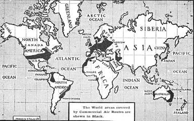
https://en.wikipedia.org/wiki/File:The_World_areas_covered_by_Commercial_Air_Routes.jpg
JANUARY 1925
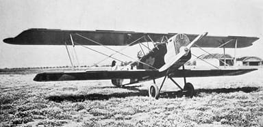
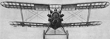
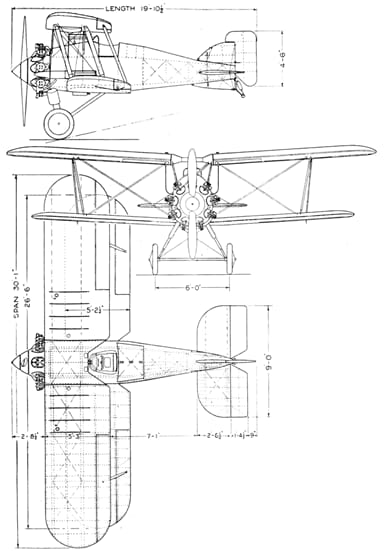
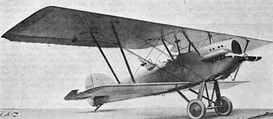
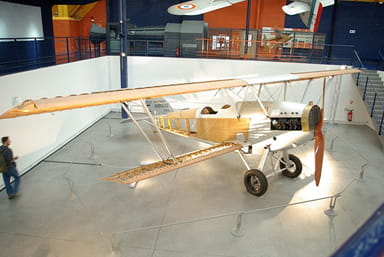
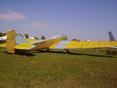
Czechoslovak Aero A.11 Light Bomber / Reconnaissance Biplane
The Aero A.11 was a light bomber and reconnaissance biplane that formed the basis for several future military developments. Around 250 were made after it first flew in 1925. Some were still in service at the outbreak of World War II, 14 years later.This was actually a derivative of the earlier Aero A.12 despite the numbering sequence.
https://commons.wikimedia.org/wiki/File:Aero_A-11_(1924).jpg
The Aero A.11, manufactured by Aero Vodochody near Prague maintained many traditional features. Such as tandem, open-air cockpits, fixed undercarriage, and slab-sided fuselage supported between two wings.
The A.11HS variant shipped to Finland in small numbers. These also saw service at the outbreak of war. However, by 1940 all were superseded and discarded.
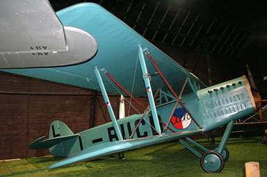
https://en.wikipedia.org/wiki/File:Replica_Aero_Ab-11_L-BUCD_(8236059976).jpg
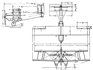
The specification of the Ab.11 light bomber version was as follows:
- Length 27 ft, height 10 ft, wing span 42 ft, wing area 393 sq ft
- Empty weight 2,381 lb, gross weight 3,501 lb, crew two
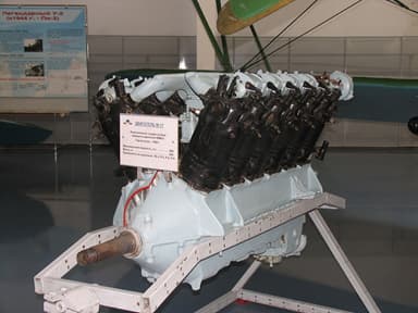
- Breitfield-Danek Perun II 6-cylinder water-cooled piston engine, 240 hp
- Max speed 134 mph, cruise 120 mph, ceiling 23,000 ft, 752 ft / min
- Forward firing 0.303 inch Vickers machine gun, bomb load 441 lb
- Two 0.303 inch Lewis machine guns in flexible mount for observer
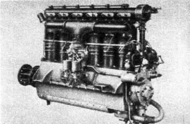
https://www.armedconflicts.com/Praga-Perun-II-t70744
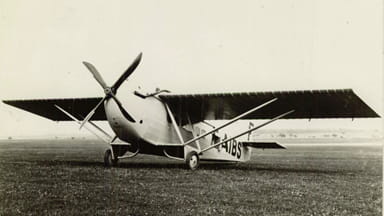
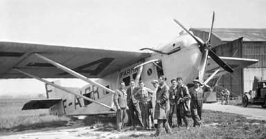
French Farman F.170 Jabiru Single Engine Airliner
The Farman F.170 Jabiru passenger airliner was an offshoot of the Farman F.120 single engine biplane bomber. The company developed it in response to growing interest in passenger air transport.
The short cut was not entirely successful as Farman only sold 18 examples. However, of these at least 5 were still flying when Air France airline incorporated in 1933.
Farman F.170 3 from NACA Aircraft Circular No.12
https://en.wikipedia.org/wiki/File:Farman_F.170_photo_NACA_Aircraft_Circular_No.12.png
The 1920’s saw a shift from multi-engine airplanes to single-motor versions. Popular reasoning held this made maintenance simpler. And besides, since most multi-engine airplanes could not stay aloft with one feathered engine, what was the point of the extra expense.
The F.170 was an awkward-looking sesquiplane with the lower wing only providing support to the upper one, and the undercarriage. Some locals derisively called it the ventre-à-terre (belly to the ground) because the wood-and-fabric fuselage had restricted ground clearance.
https://www.baaa-acro.com/aircraft/farman-f170-jabiru
The specification of the Farman F.170 was as follows:
- Length 38.5 ft, height 10.5 ft, wing span 52.5 ft, wing area 565 sq ft
- Empty weight 3,968 lb, gross weight 7,055 lb, crew one, eight passengers
- Farman 12 We W-12 water-cooled piston engine, 500 hp
- Max speed 140 mph, cruise 110 mph, range 310 mi, ceiling 14,800 ft
https://en.wikipedia.org/wiki/Farman_12We#/media/File:Flugwerft_Schlei%C3%9Fheim_6.jpg
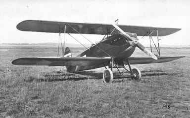
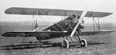
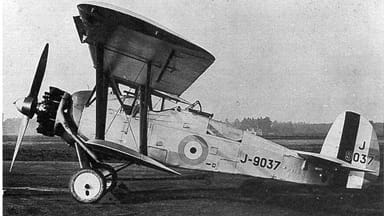
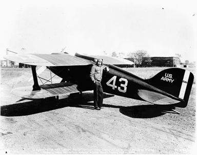
Czechoslovak Avia BH-21 Biplane Fighter / Racer
The Avia BH-21 helped the Czech nation secure its national security, while also winning several competitions as an accomplished racer. Manufacturer Avia sold 139 airplanes to the national air force, as well as 45 to Belgium after the first flight in January 1925.
https://en.wikipedia.org/wiki/File:Avia_BH-21.jpg
The Avia BH-21 was designed in response to a Czechoslovak Defense Department requirement for a new fighter aircraft. The military turned down the original Avia BH-17 offer, but accepted the subsequent BH-21 with straightened interplane bracing, and a better field of vision for the pilot. There was also a training version, the BH-22.
While the aircraft saw no active service on military missions, it was an important stepping stone to the more advanced BH-33 and B-34 types. Experimental versions BH-21J and BH-21R won several national air race competitions in 1925.
https://commons.wikimedia.org/wiki/File:Avia_BH-21J_s_motorem_Jupiter_IV.jpg
The specification of the base model Avia BH-21 was as follows:
- Length 22.5 ft, height 9 ft, wing span 29 ft, wing area 240 sq ft
- Empty weight 1,687 lb, gross weight 2,370 lb, crew one
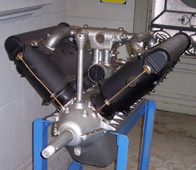
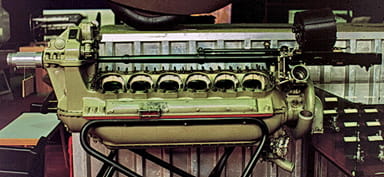
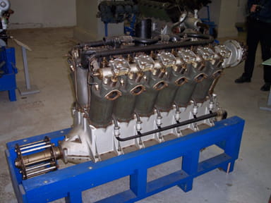
- Hispano-Suiza 8Fb V-8 water-cooled piston engine, 300 hp at 1,850 rpm
- Max speed 160 mph, stall speed 56 mph, range 370 mi, 23,000 ft in 35 min
- Two 0.303 inch Vickers machine guns in the upper front fuselage
https://en.wikipedia.org/wiki/Hispano-Suiza_8#/media/File:Hispano_Suiza_8_A_Brussel.jpg
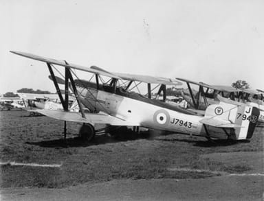
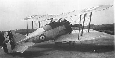
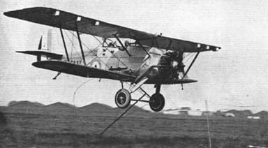
British Fairey Fox Light Bomber Fighter Biplane
The Fairey Fox Mark 1 first flew on January 3, 1925, when it quickly demonstrated good performance and handling. But the Royal Air Force was disinterested because the fuel tanks were inside the fuselage, and it featured an American engine. However, the chief of the air staff relented after a demonstration and ordered a squadron of 18 Foxes.
https://commons.wikimedia.org/wiki/File:12_Squadron_RAF_Fairey_Foxes_Hendon_1929_IWM_H(AM)_162.jpg
The first generation Fairey Foxes were 50 mph faster than other British contemporary fighters. In fact, pilots were instructed to fly no faster than 140 mph during annual Air Defense Exercises in order to give the ‘defending fighters’ a chance.
However, the Royal Air Force only purchased a total 25 aircraft before insisting Fairey move on from the American motor. Subsequent versions survived in Belgium into the outbreak of World War II, although they were no match for the German Messerschmitt Bf 109.
https://en.wikipedia.org/wiki/File:Fairey_Fox.jpg
The specification of the Fairey Fox VIR was as follows:
- Length 30.5 ft, height 11.5 ft, wing span 38 ft, wing area 362 sq ft
- Empty weight 2,920 lb, gross weight 5,170 lb, crew two
- Hispano-Suiza 12Ybrs V-12 liquid-cooled piston engine, 860 hp
- Max speed 224 mph, range 634 mi, ceiling 32,800 ft, 6.5 min to 16,400 ft
- Two forward firing machine guns, one rear gun, 220 pound bomb load
https://en.wikipedia.org/wiki/Hispano-Suiza_12Y#/media/File:Hs12_Ydrs.jpg
FEBRUARY 1925
French aviators Henri Lemaître and Ludovic Arrachart set a new world distance record in a Breguet 19 G.R. They fly 1,967 miles from Étampes in Paris, France, to Villa Cisneros in Spanish Sahara.
Sabena airline establishes the first air connection between Belgium and the Belgian Congo, pioneering a long-haul route to Léopoldville.
British Gloster Gamecock Biplane Fighter Aircraft
The Gloster Gamecock was a spin-off from the Mk III Grebe, and first flew in February 1925. It entered service in May 1926, although this only continued through to July 1931. That’s because improved ailerons and refined fuselage contours failed to prevent 22 losses in landing / spin accidents.
https://en.wikipedia.org/wiki/File:Gloster_Gamecock.jpg
The Mark II version featured a longer upper wing, and a modified tail unit that improved stability. Gloster manufactured 108 Gamecocks, of which a number entered the Finnish Air Force. The Imperial Japanese Navy also flew about 150 carrier versions manufactured under license between 1929 and 1935.

https://commons.wikimedia.org/wiki/File:Gloster_Gamecock_structure_Aero_Digest_December,1930.jpg
The specification of the Gloster Gamecock Mk I version was as follows:
- Length 19,5 ft, height 9.5 ft, wing span 29.5 ft, wing area 264 sq ft
- Empty weight 1,930 lb, gross weight 2,860 lb, crew one
- Bristol Jupiter VI 9-cylinder air-cooled radial piston engine, 425 hp
- Max 155 mph, endurance 2.5 hrs, ceiling 22,100 ft, 10,000 ft in 7.5 min
- Two 0.303 inch Vickers internally-mounted machine guns

https://en.wikipedia.org/wiki/Gloster_Gamecock#/media/File:Gloster_Gamecock_II_3-view_L’Air_August_15,1927.png
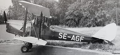
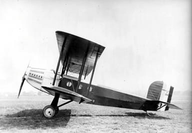
British de Havilland Moth DH.60 Training and Touring Aircraft
The de Havilland Moth DH.60 first flew on February 22 1925, when it heralded a series of light aircraft, sports planes and military trainers. They were the most common civil aircraft flying in Britain in the late 1920s and 1930s. During that time, every light aircraft flying in the UK was commonly referred to as a Moth, regardless whether de Havilland built it or not.
https://upload.wikimedia.org/wikipedia/commons/5/5e/SE-AGF_DH_60_Moth.jpg
The Moth DH.60 was a conventional two-seat biplane of wooden construction, with a plywood-covered fuselage and fabric-clad surfaces, and a standard tail plane. However, it had folded wings enabling owners to hangar their aircraft in much smaller spaces. And it soon proved popular with private owners.
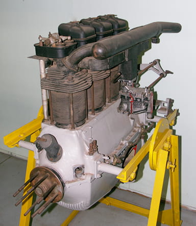
But Geoffrey de Havilland was dissatisfied with the original ADC Cirrus engine, because it used components salvaged from World War I Renault engines and supply was limited. And so he decided to replace it with the British de Havilland Gipsy I engine which he could build in-house on a production-line, side by side with Moth airframes.
https://en.wikipedia.org/wiki/File:Amy_Johnson_jason_india.jpg
The specification of the later DH.60G Gipsy Moth was as follows:
- Length 24 ft, height 8.5 ft, wing span 20 ft, wing area 243 sq ft
- Empty weight 920 lb, max take-off weight 1,650 lb, crew two
- De Havilland Gipsy I 4-cylinder air-cooled in-line piston engine, 100 hp
- Max 102 mph, cruise 85 mph, range 320 mi, ceiling 14,500 ft, climb 500 ft / min
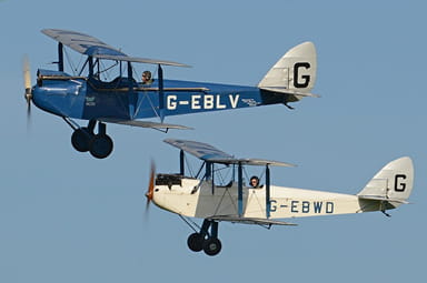
https://en.wikipedia.org/wiki/File:DH60_Moths_%27G-EBLV%27_%26_%27G-EBWD%27._Old_Warden,_17-6-2017_(30205705947).jpg
https://en.wikipedia.org/wiki/De_Havilland_Gipsy#/media/File:De_Havilland-Gipsy_II-001.jpg
MARCH 1925
Huff-Daland Dusters establishes the world’s first crop dusting company. It becomes Delta Air Service, then Delta Air Corporation, and finally Delta Air Lines
United States Huff-Daland Duster Light Biplane
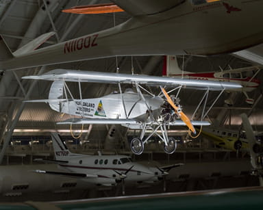
By the mid-1920’s, entrepreneurs not directly related to the aviation industry were imagining new uses for airplanes which were becoming trustworthy and reliable. The Huff-Daland Duster was a new way to control the boll weevil insect infestation, then destroying America’s cotton crops.
After all, if you can bomb a human enemy, the U.S. Department of Agriculture reasoned, then why not drop clouds of poisonous dust on boll weevils from high in the sky. Huff-Daland Aero Corporation then building light bombers accepted the challenge, and so a new industry was born.
http://www.aerofiles.com/_huff.html
The Huff-Daland Duster had a fuselage made of steel tubes, and wooden wings both covered with fabric as was the custom at the time. It was part of a series of aircraft that did duty as military bombers / observers, and civilian light cargo and passenger aircraft.
Others morphed into seaplanes, camera planes, and even aerial ambulances. Huff-Daland provided further proof that aircraft had a role in mainstream American culture.
https://airandspace.si.edu/collection-objects/huff-daland-duster/nasm_A19680235000
The specification of the Huff-Daland Duster was as follows:
- Length 26 ft, height 8.5 ft, wing span 33 ft, crew two
- Empty weight 1,420 lb, gross 2,255 lb, max speed 112 mph
- Wright Whirlwind air cooled, radial nine-cylinder J-4 engine, 200 hp
https://airandspace.si.edu/collection-objects/huff-daland-duster/nasm_A19680235000
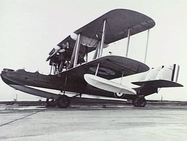
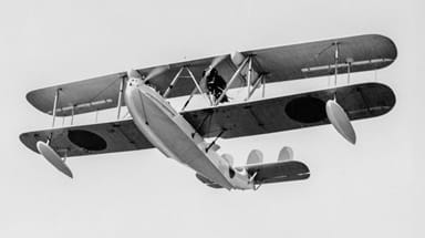
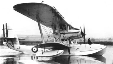
British Supermarine Southampton Flying Boat
The Supermarine Southampton was a large flying boat derived from the experimental Supermarine Swan. It represented a new standard for maritime aircraft. Demand was so great Supermarine had to expand its production capacity to keep up, and 83 were sold between 1924 and 1934.
https://en.wikipedia.org/wiki/File:RAAF_Supermarine_Southampton_(044869).jpg
The Southampton Mk I had both its hull and wings manufactured from wood, while the Southampton Mk II had a hull with a single thickness of duralumin instead. This latter refinement reduced the dry fuselage weight by 500 pounds (plus 400 pounds less water soaked up). Taken together, these increased the flying rage by 200 miles.
While the British Royal Airforce was the major customer, Supermarine also sold military Southampton’s to Argentina, Australia, Denmark, Japan, and Turkey, while Japan Air Transport and Imperial Airways used them occasionally in small numbers.
https://commons.wikimedia.org/wiki/File:Supermarine_Southampton_Mk.II_1933.jpg
https://commons.wikimedia.org/wiki/File:Supermarine_Southampton_cockpit,_RAF_Museum,_Hendon._(11329560266).jpg
The specification of the Supermarine Southampton II was as follows:
- Length 50 ft, height 20.5 ft, wing span 75 ft, wing area 1,448 sq ft
- Empty weight 9,697 lb, gross weight 14,400 lb, crew four
- Two Napier Lion VA inline 12-cylinder W-block engines 500 hp each
- Max speed 95 mph, range 544 mi, endurance 6.3 hours, ceiling 8,100 ft
- Three 0.303 inch Lewis guns, one in bows, two amidships, 1,100 bomb load
https://www.baesystems.com/en/heritage/vickers-supermarine-type-541-swift
APRIL 1925
Imperial Airways presents the first inflight entertainment by screening ‘The Lost World’ movie on a trip between London and Europe.
Maurice Drohan wins the Peix Solex prize by flying a Salmson 3 additive-powered Farman Aviette for 75 miles using less than 6.6 pounds weight of gasoline and oil.
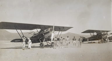
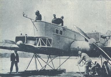
Italian aviator Francesco de Pinedo and his mechanic Ernesto Campanelli leave Rome on a 210-day flight in a SIAI S.16ter flying boat. It will take them to Australia and Japan, before they return to Rome in November.
German Junkers J29 Monoplane with “Double Wing” Control
The Junkers J29 was a small, aerodynamically clean, low wing cantilever monoplane intended to be a trainer. However, it was not a commercial success if that ever was Junkers’ intention. Its true purpose in hindsight was to test the company’s new Double Wing (Doppelflügel) control surface, which made a significant contribution to fixed-wing flight.
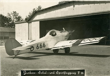
https://www.wikidata.org/wiki/Q685560#/media/File:T29.jpg
The J29 airframe followed Junkers’ standard practice of covering the duralumin-tube framework with corrugated sheets of the same material. The wings were straight tapered, almost entirely on the trailing edge, and had nearly square tips. While the fuselage was flat-sided with curved decking.
However, the wing control surfaces were a new innovation. Because the ailerons were separate and full span, but secured by a hinge system forming slots between the wings. This arrangement exposed the entire control surface cross-section to the slipstream.
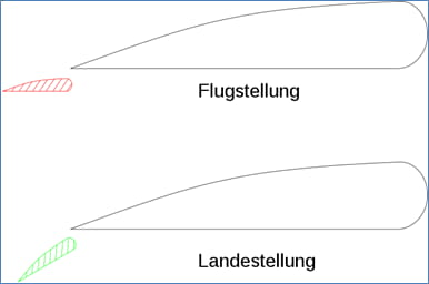
https://commons.wikimedia.org/wiki/File:Junkers_Doppelfl%C3%BCgel_Prinzip_vector.svg
This ‘double wing system’ enabled the full-width ailerons to assume two roles. In normal flight, they regulated the longitudinal alignment of the aircraft. However, they could be lowered during landing while still allowing the pilot to trim the angle. Later Junkers aircraft including the G 28, the Ju 52/3m and the Ju 87 used the system.
The specification of the Junkers J29 was as follows:
- Length 23.5 ft, height 7.5 ft, wing span 37.5 ft, wing area 191 sq ft
- Empty weight 1,080 lb, gross weight 1,653 lb, crew one, one passenger
- Junkers L1a 6-cylinder upright air-cooled inline engine, 83 hp
- Max speed 87 mph, cruise 68 mph, range 290 mi, ceiling 8,200 ft
https://commons.wikimedia.org/wiki/File:Junkers_Ju_52_3m_Doppelfluegel.jpg
MAY 1925
The Imperial Japanese Army Air Corps sets up as a separate unit. It has 3,700 personnel and about 500 aircraft upon commissioning.
JUNE 1925
A United States Coast Guard Vought UO-1 becomes the first aircraft to pursue a ‘rum-runner’ smuggler hoping to beat prohibition. It assists with their capture four days later.
British Gloster Gamecock Biplane Fighter Aircraft
The Gloster Gamecock was a spin-off from the Mk III Grebe and first flew in February 1925. It entered UK service in May 1926, although this only continued until July 1931. That’s because improved ailerons and refined fuselage contours failed to prevent 22 losses in landing or spin accidents.

https://en.wikipedia.org/wiki/File:Gloster_Gamecock.jpg
The Mark II version featured a longer upper wing, and modified tail unit and these improved stability. Gloster manufactured 108 Gamecocks, of which a number entered the Finnish Air Force. The Imperial Japanese Navy also flew about 150 carrier versions, manufactured under license between 1929 and 1935.
https://commons.wikimedia.org/wiki/File:Gloster_Gamecock_structure_Aero_Digest_December,1930.jpg
The specification of the Gloster Gamecock Mk1 version was as follows:
- Length 19.5 ft, height 9.5 ft, wing span 29.5 ft, wing area 264 sq ft
- Empty weight 1,930 lb, gross weight 2,860 lb, crew one
- Bristol Jupiter VI 9-cylinder air-cooled radial piston engine, 425 hp
- Max 155 mph, endurance 2.5 hrs, ceiling 22,100 ft, 10,000 ft in 7.5 min
- Two 0.303 inch Vickers internally-mounted machine guns
https://en.wikipedia.org/wiki/Gloster_Gamecock#/media/File:Gloster_Gamecock_II_3-view_L’Air_August_15,1927.png
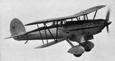
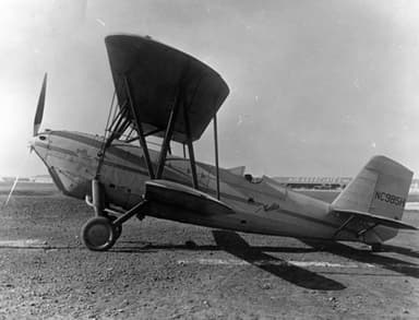
French Potez 25 Twin-Seat, Single-Engine Biplane Fighter Bomber
The Potez 25 was one of the most successful military aircraft of the late 1920s and early 1930s. Some 4,000 were built, including 2,300 in France after prototyping in May 1925. It became the standard multi-purpose aircraft of over 20 air forces, including French, Polish and American. Some lasted into the 1940s.
https://commons.wikimedia.org/wiki/File:Potez_25_L%27A%C3%A9rophile_January,1926.jpg
The Potez 25 (Potez XXV) succeeded where others failed because it was versatile. It was equally at home in pursuit fighting, light bombing, and doing reconnaissance flights. Civilian operators also chose it for commercial operations, particularly mail transport companies.
The Potez 25 prototype, completed in 1925 was a sesquiplane with a shorter lower wing, as opposed to a traditional biplane. Potez entered it in a number of competitions to highlight the advantages over cheap, demobilized aircraft. It won both the European and Mediterranean Rallies both over 4,000 miles in distance.
https://en.wikipedia.org/wiki/File:Potez_25_1_(MAE).JPG
The specification of the Potez 25 was as follows:
- Length 30 ft, height 12 ft, wing span 46.5 ft, wing area 500 sq ft
- Empty weight 3,020 lb, gross weight 5,498 lb, crew two
- Gnome & Rhône 9Ac 9-cylinder air-cooled radial piston engine, 320 hp
- Max speed 140 mph, 441 pound bomb load below wings
- Two forward-facing 0.303 inch Vickers machine guns
- One 0.303 inch Lewis gun mounted flexibly in rear cockpit
https://commons.wikimedia.org/wiki/File:Potez_sur_le_terrain_Ounianga_1941.jpg
American Douglas C-1 Military Cargo / Transport Aircraft
The Douglas C-1 was a cargo / transport workhorse designed for, and delivered to the United States Army Air Service starting in 1925. Some 26 were built after first flying on May 2, 1925. It performed various roles, including as engine testbed, as a prototype air ambulance, and as refueling a modified Atlantic-Fokker C-2A transport airplane for early air-to-air refueling experiments.
https://www.nationalmuseum.af.mil/Upcoming/Photos/igphoto/2000571014/
The Douglas C-1 built on ideas from several earlier and similar designs developed by Douglas in the early 1920s, including the Douglas World Cruiser. It featured an enclosed passenger compartment with auxiliary door, capable of carrying six passengers or about 2,500 lb of cargo.
However, in addition it also had a trap door in the lower fuselage to allow large and / or heavy cargo (particularly aircraft engines) to be lifted directly into the cargo compartment. The United States Army Air Corps ordered additional, slightly larger versions in 1926 and 1927.
https://en.wikipedia.org/wiki/File:Atlantic_C-2A_refuelled_by_Douglas_C-1_USAF.JPG
The specification of the Douglas C-1 was as follows:
- Length 35.5 ft, height 14 ft, wing span 56.5 ft, wing area 805 sq ft
- Empty weight 3,836 lb, gross weight 6,442 lb, crew two, six to eight passengers
- Liberty V-1650-1 V-12 water-cooled piston engine, 435 hp
- Max 116 mph, cruise 85 mph, range 385 mi, ceiling 14,850 ft, climb 645 ft / min
https://en.wikipedia.org/wiki/Liberty_L-12#/media/File:Liberty_L-12-1.jpg
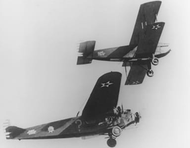
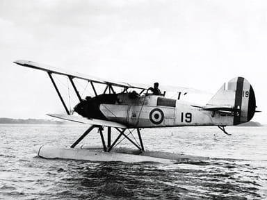
British Armstrong Whitworth Atlas Army Co-operation Aircraft
The Armstrong Whitworth Atlas was the Royal Airforce’s first purpose-built army co-operation aircraft. This meant the single-engine biplane had to merge the roles of artillery spotter aircraft, liaison, reconnaissance plane, and close air support. The Whitworth Atlas was clearly a success, because Armstrong Whitworth built 478 after the first flight on May 10, 1925.
https://en.wikipedia.org/wiki/File:AW_Atlas.jpg
Whitworth Armstrong designed the aircraft to replace aging DH.9A and Bristol Fighter airplanes, but also intended it to work with its Ajax and Aries counterparts. The military agreed it met the requirements of Specification 20/25, but delayed deliveries until teething problems were sorted out.
These centered on inability to slip sideways without turning, which the manufacturers attempted to solve with sweptback metal wings. However, this was at the cost of handling and stalling. The designers cured this by increasing the sweep back of the wings, and adding automatic leading edge slats.
https://en.wikipedia.org/wiki/File:AWAries.jpg
The specification of the Armstrong Whitworth Atlas I was as follows:
- Length 28.5 ft, height 10.5 ft, wing span 39.5 ft, wing area 391 sq ft
- Empty weight 2,550 lb, gross weight 4,020 lb, crew two
- Armstrong Siddeley Jaguar IVC 14-cylinder two-row radial engine, 450 hp
- Max 142 mph, endurance 3.25 hrs, ceiling 16,800 ft, 5.5 min to 5,000 ft
- One forward firing 0.303 inch Vickers machine gun, four 112 pound bombs
- One 0.303 inch Lewis Gun on a scarff ring in the rear cockpit
https://en.wikipedia.org/wiki/Armstrong_Whitworth_Atlas#/media/File:RCAF_-_Armstrong_Whitworth_Atlas_Mk.1_floatplane.jpg
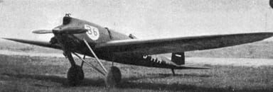
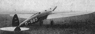
German Bäumer B II Sausewind Fully Streamlined Monoplane
Sausewind means ‘Rushing Wind’ in German, and manufacturer Bäumer Aero came close to expressing the idealized freedom of flight in his creation. Chief designer / owner Paul Bäumer was a master of reinvention, having evolved from wartime fighter ace, through dentist to airplane manufacturer. And his Bäumer II Sausewind turned aircraft design equally on its head.
https://commons.wikimedia.org/wiki/File:B%C3%A4umer_Sausewind_L%27Aerophile_Salon_1932.jpg
The aerobatic, 2-seat monoplane racer / tourer boasted a perfect wooden elliptical wing, seamlessly attached to a smooth, plywood monocoque fuselage, with similar elliptical vertical and horizontal tail surfaces. Even the designers of the Supermarine Spitfire aircraft praised its brilliance and style ten years later.
They only ever built one Bäumer Sausewind, which first took to the air on May 26, 1925. Although the concept did help co-designer Walter Gunter mold the Heinkel He 70 Blitz high-speed transport eight years later. The complete absence of wing braces set the compass for future aircraft design. The airplane established a number of world records between 1925 and 1927.
https://commons.wikimedia.org/wiki/File:B%C3%A4umer_Sausewind_Les_Ailes_July_21,1927.jpg
The specification of the Bäumer Sausewind was as follows:
- Length 20 ft, wing span 30.5 ft, wing area 125 sq ft
- Empty weight 617 lb, gross weight 1,080 lb, crew two
- Wright Lawrence L4 piston engine, 61 hp
- Maximum speed 110 mph, climb 590 ft in 3 min

https://commons.wikimedia.org/wiki/File:B%C3%A4umer_Sausewind_3-view_Les_Ailes_July_21,1927.png
https://commons.wikimedia.org/wiki/File:Wright_Lawrance_L4.jpg
JULY 1925
The United States Post Office Department inaugurates a 24-hour transcontinental air mail service. A coast-to-coast system of lighted beacons eliminates the need for trains at night.
Western Air Express (later merged with Delta Airlines in 1980s) incorporates, and receives the United States Post Service contract for the 650-mile Contract Air Mail Route from Salt Lake City, Utah, to Los Angeles.
American Modified Douglas O-2 DAM-1 Postal Service Biplane
The United States Post Service decided to modernize its fleet of de Havilland DH.4 biplane variants in 1925. It ordered the first of 57 specially modified Douglas O-2 aircraft after successful trials in July 1925, and moving the pilot into what had been the observer’s cockpit to free space up front for cargo.
https://www.deltamuseum.org/about-us/blog/from-the-hangars/2014/01/14/artifact-spotlight-western-air-express-douglas-m-2-model
The DAM 1’s – as the Douglas O-2 specials were named – were a conventional design that soon attracted orders. The M-2 versions that followed replaced the previous ‘tunnel radiator’ with a frontal cooling system.
A number of varieties followed including converting the payload area back to an open passenger cockpit. The various derivatives performed well enough. However, they were superseded in 1928 by three-engine aircraft capable of heavier loads.
https://www.deltamuseum.org/about-us/blog/from-the-hangars/2014/01/14/artifact-spotlight-western-air-express-douglas-m-2-model
The specification of the later, extended wing-span Douglas M-4 version was as follows:
- Length 29 ft, height 10 ft, wing span 44.5 ft, wing area 465 sq ft
- Empty weight 3,405 lb, gross weight 4,900 lb, crew one
- Max 140 mph, cruise 110 mph, range 700 mi, ceiling 16,500 ft, climb 1,000 ft / min
https://en.wikipedia.org/wiki/File:Douglas_M-4_L%27Ann%C3%A9e_a%C3%A9ronautique_1926.jpg
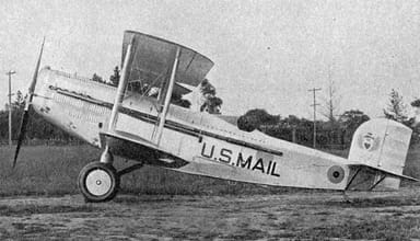
United States Boeing Model 40 Single Engine Mail Biplane
United States postal air services were expanding rapidly in the mid-1920s, especially after a system of beacons made night flying reliable. The Boeing Model 40 was a response to a U.S. Post Office decision to replace its aging fleet of ex-military de Havilland DH.4 aircraft.
https://en.wikipedia.org/wiki/File:Model40.jpg
The Boeing 40 first flew on July 20, 1925 under power of the stipulated water-cooled Liberty V12 engine as used by the DH-4, of which large stocks of war-built engines were available. It was a conventional biplane design with streamlined cowling with an underslung radiator. It was also Boeing’s first aircraft designed to carry passengers.
The fuselage had a steel tube structure with aluminum and laminated wood covering, while the wings and tail were wooden construction. The U.S. Post Office purchased the prototype, although the main order went to the specially modified Douglas O-2 offering. Subsequent privatization of air routes ensured Boeing later sold approximately 80 of the aircraft.
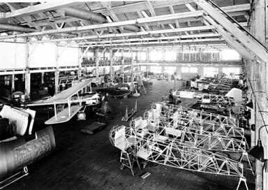
https://commons.wikimedia.org/wiki/File:Boeing_Airplane_Co._plant_interior,_Seattle,_Washington_(4861195812).jpg
The specification of the Boeing model 40A was as follows:
- Length 33 ft, height 12 ft, wing span 44 ft, wing area 547 sq ft
- Empty weight 3,531 lb, max take-off 6,000lb, crew one, two passengers, 1,200 lb mail
- Pratt & Whitney Wasp 9-cylinder air cooled radial engine, 420 hp
- Max 128 mph, cruise 105 mph, range 650 mi, ceiling 14,500 ft, climb 770 ft / min
https://en.wikipedia.org/wiki/Boeing_Model_40#/media/File:Boeing_Pax40c.jpg
AUGUST 1925
French aviators Jules Landry and Maurice Drouhin set a closed-circuit distance record of 2,732 miles in 45 hours 11 minutes in a Farman F.62
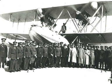
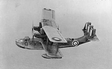
British Short Singapore Multi-Engine Biplane Patrol Flying Boat
The Short Singapore flying boat became Royal Air Force’s main long-range maritime patrol flying boat in the 1930’s, and also saw service with Royal New Zealand Air Force against Japan during World War II. There were three versions, namely the Singapore I and II prototypes, and the Singapore III production model.
https://en.wikipedia.org/wiki/File:Short_Singapore_I.jpg
The prototype was a two-engine, metal-hull version of the wood-hulled Short Cromarty. It first flew on August 17, 1926, whereafter it completed a survey flight around Africa. Lessons learned from this inspired push-pull four-engine production version with triple tail fins.
Thirty-seven of the aircraft were built for the Royal Air Force, of which 4 transferred to New Zealand in 1941. The six crew were housed in a central cabin, and in fore, aft, and midships open gun positions. The last aircraft were finally phased out in New Zealand in 1943.
https://en.wikipedia.org/wiki/File:Aircraft_of_the_Royal_Air_Force_1939-1945-_Short_S.19_Singapore_CH2556.jpg
The specification of the Short Singapore III was as follows:
- Length 64 ft, height 23.5 ft, wing span 90 ft, wing area 465 sq ft
- Empty weight 20,364 lb, max take-off 32,390 lb, crew six to seven
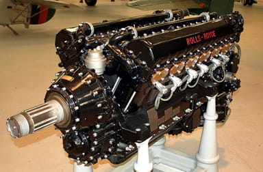
- Four Rolls-Royce Kestrel VIII/IX liquid-cooled V12 engines, 610 hp each @ 4,500 ft
- Max 136 mph, cruise 104 mph, range 1,000 mi, ceiling 14,800 ft, 7 min to 5,000 ft
- Three 0.303 inch Lewis guns in nose, waist and tail, 1,100 pound bomb load
https://en.wikipedia.org/wiki/File:RRKestrelXVI.JPG
SEPTEMBER 1925
A Czechoslovakian Avia BH-21R racer wins the Czechoslovakian national air races. It completes the 120-mile course at an average speed of 186 mph.
Bolivian airline Lloyd Aéreo Boliviano begins flight operations, flying a Junkers F.13 which takes off from Cochabamba, Bolivia.
The Society of Automotive Engineers hosts the First Annual Aerial Reliability Tour, with prizes for completing the 1,900-mile course stopping at 10 U.S. midwest cities. Among the 17 entrants, 11 obtain perfect scores.
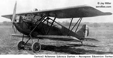
American Curtiss Carrier Pigeon Single Engine Biplane, Mail Plane
Some say the Curtis Carrier Pigeon was the first aircraft designed specifically for the U.S. Airmail Service. Curtis designed it, apparently from scratch to replace the service’s aging fleet of eight-year-old converted Airco D.H.4 biplanes. The government selected the specially modified Douglas O-2 aircraft instead, although some private contractors preferred the Curtiss offering.
https://commons.wikimedia.org/wiki/File:AL79-038_Curtiss_Carrier_Pigeon_2_NC985H_(14121352800).jpg
The Carrier Pigeon had a welded-steel, fuselage frame covered with fabric. The upper and lower wings were interchangeable, and used solid, un-spliced spruce spars. The rudder, ailerons, and elevators were also interchangeable, which reduced spares holdings.
Curtis positioned the watertight cargo hold at the center of gravity, so the aircraft could accommodate a range of loads without affecting the balance. A seven-quart capacity fire extinguisher was plumbed to the engine compartment for suppression of in-flight fires. The pilot could choose between wheel- or stick-control based on their preference.
https://en.wikipedia.org/wiki/File:Curtiss_Carrier_Pigeon_II.jpg
The specification of the Curtiss Model 40 – Carrier Pigeon I was as follows:
- Length 28.5 ft, height 12 ft, wing span 42 ft, wing area 505 sq ft
- Empty 3,603 lb, max take-of 5,620 lb, crew one, 1,000 lb cargo load
- Liberty L-12 water-cooled V12 engine, 400 hp
- Max 125 mph, cruise 105 mph, range 525 mi, climb rate 800 ft / min
https://en.wikipedia.org/wiki/Curtiss_Carrier_Pigeon#/media/File:Curtiss_Carrier_Pigeon_3-view_L’A%C3%A9ronautique_March,1927.png
OCTOBER 1925
A British airship successfully launches a de Havilland DH.53 Humming Bird piloted by Flying Officer Campbell MacKenzie-Richards and Flying Officer Riggs in flight.
An Air Union Farman F.60 Goliath crashes during a scheduled passenger flight from England to Paris, France. Three of the six people aboard die, while two suffer injuries.
French aviator Joseph Sadi-Lecointe wins the Beumont Cup in a Nieuport-Delage NiD 52, achieving a speed of 194 mph.
Jimmy Doolittle of United States Army Service wins the 1925 Schneider Trophy in a Curtiss R3C-2 at an average speed of 232 mph.
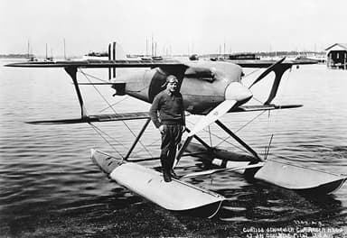
American Curtiss R3C Record-Breaking Float Plane / Land Plane
The Curtiss R3C was a racing aircraft built in both landplane, and floatplane form. The R3C-1 landplane won the 1925 Pulitzer Trophy Race with a speed of 248 mph, while the R3C-2 seaplane scooped the 1925 Schneider Trophy at 232 mph. The latter aircraft achieved 245 mph the following day on a straight course.
https://www.thisdayinaviation.com/tag/curtiss-r3c-2/
The Curtiss R3C had a fuselage constructed of four ash longerons, and seven birch vertical bulkheads. Curtiss enclosed this with two layers of thick spruce strips. These were placed on a 45° diagonal from the fuselage horizontal centerline, with the second layer at 90° to the first, covered over with doped fabric.
The wings and tail surfaces were also made of wood, with spruce ribs and a covering of spruce strips. The single-bay wings were wire braced, and contained surface radiators made of thin brass sheeting. This arrangement reduced aerodynamic drag.
https://en.wikipedia.org/wiki/File:Curtiss_Racer_NASA_GPN-2000-001310.jpg
The specification of the Curtiss R3C-2 seaplane was as follows:
- Length 22 ft, height 10.5 ft, wing span 22 ft, wing area 144 sq ft
- Empty weight 2,135 lb, gross weight 2,738 lb, crew one
- Curtiss V-1400 D-12 V-12 water-cooled piston engine, 565 hp
- Maximum speed 245 miles per hour, range 290 miles
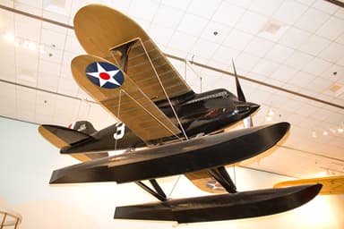
https://en.wikipedia.org/wiki/Curtiss_R3C#/media/File:Curtiss_R3C2_at_NASM.png
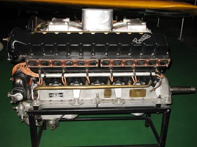
https://en.wikipedia.org/wiki/Curtiss_D-12#/media/File:Curtiss_D-12_2.jpg
NOVEMBER 1925
Italian aviator Francesco de Pinedo and his mechanic Ernesto Campanelli return to Rome, at the end of their 201-day, 35,000-mile journey via Australia and Japan in a SIAI S.16ter flying boat.
Russian Tupolev TB-1 Angular Monoplane Bomber
The Tupolev TB-1 was the production version of the ANT-4 prototype that first flew on November 26, 1925. It was the first large all-metal aircraft the Soviet Union built. Tupolev manufactured 218 between 1929 and 1932.
The last ones were finally retired in 1948. Some were fitted with floats for use as torpedo bombers under model TB-1P, and for aerial survey operations.
https://commons.wikimedia.org/wiki/File:Tupolev_TB-1_Strana_Sovyetov-2.jpg
The Tupolev team designed a twin-engine, all-metal monoplane with a corrugated duralumin skin. This derived from Tupolev’s earlier work utilizing the all-metal aircraft design techniques first pioneered by Hugo Junkers in 1918. The first flight was successful.
However, production was delayed while they found a suitable, but affordable engine. Thereafter, the ex-Junkers factory at Fili, Moscow began production. The Tupolev TB-1 became a Soviet Union mainstay bomber, until the much larger, four-engine Tupolev TB-3 replaced it. Many were recycled as G-1 civil freighters for Aeroflot and Aviaarktika. Others were used for experimental purposes.
https://en.wikipedia.org/wiki/File:Zveno-1.jpg
The specification of the Tupolev TB-1 was as follows:
- Length 59 ft, height 16.5 ft, wing span 94 ft, wing area 1,300 sq ft
- Empty weight 9,964 lb, gross weight 15,013 lb, crew six
- Two Mikulin M-17 V-12 water-cooled piston engines, 680 hp each
- Max 111 mph, cruise 97 mph, range 620 mi, ceiling 15,850 ft, climb 596 ft / min
- Six Degtyaryov machine guns, 2,205-pound bomb load
https://en.wikipedia.org/wiki/Tupolev_TB-1#/media/File:ANT-4_in_Ulyanovsk_Aircraft_Museum.JPG
https://en.wikipedia.org/wiki/Mikulin_M-17#/media/File:Mikulin_M-17.jpg


.jpg)
.jpg)
_162.jpg)
.jpg)
.jpg)
.jpg)
.JPG)
.jpg)
.jpg)